Guidance for Creating Civil Cells
To create the most flexible civil cells - the ones that will place correctly in as many situations as possible - there are several things to consider. Civil cells are, at a basic level, a collection of rules which are used to create the new elements. It therefore follows that the rules need to be constructed in such a way that they will always evaluate correctly when the civil cell is placed.
Using a DGNLib
If you want to be able to reuse your civil cell in different designs, create it in a DGNLib, then put it in a location that MicroStation will read when it starts up. This ensures that the civil cell will always be available.
If you intend to create a lot of civil cells, it may be worth organizing them so that you have a DGNLib for each type - for example one for junctions, and another for ramps. One reason for doing this is that it makes navigating to an individual civil cell easier as initial selection will be on the type. It may also be worth putting each individual civil cell in an appropriately named MicroStation model.
If you have created some civil elements in a DGN that you would like to be able to share in a DGNLib, then you can use the following process:
-
Create a civil cell in the DGN
-
Open the DGNLib that you want to contain the civil cell
-
Reference the DGN which contains the civil elements in to the DGNLib
-
Create elements in the DGNLib to use as reference elements
-
Use the Place Civil Cell tool to place the civil cell on these reference elements
The DGNLib will now contain the civil cell, and it can be shared as required.
Keep the content to a minimum
Consider what the civil cell really needs to contain, and include only the minimum. For example, if you are creating a civil cell for a junction, it is quite likely that it only needs to contain one reference element to represent the road edge of the main road. It should not include any corridors or other elements from the through road, because they do not belong in a junction, and they will cause extra processing. You cannot delete dependent elements in a civil cell, so any extra elements have to be deleted once the civil cell has been placed. Similarly, if the pavement construction depth changes often, then it might be easier to apply the template to model the layers after the civil cell has been placed than delete the surface template and apply a different one. If the construction depths are fairly standard though a surface template in the civil cell could be the most efficient procedure.
Choosing suitable reference elements
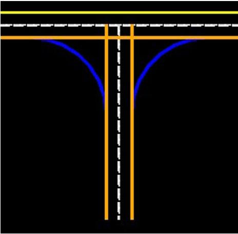
Consider the situation shown here:

If you want to create a civil cell for this intersection, then it might seem sensible to select the two dashed white lines as the references. However, this is not likely to result in the most flexible civil cell. The yellow elements (representing the road edges) have been created using the Horizontal Offset Transition tool, with the dashed white lines as the references. If you select the dashed white lines as the references, then the road edges will be included in the civil cell, which is unlikely to be what is required because the road edges will be created every time you place the civil cell. This could result in several copies of them, if you place the civil cell in several locations along a road.
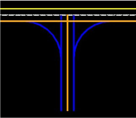
In this situation, it would be better to select the road edges as the references:
The orange lines are the selected references, and the blue lines are the elements that will be included in, and created by, the civil cell.
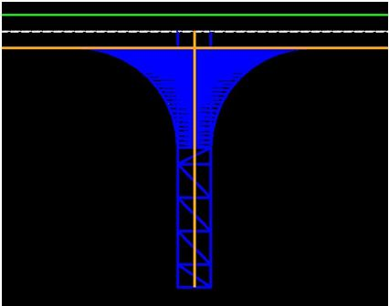
If the intersection is actually an access or a driveway, then you might want the civil cell to include the two edges. If so, then select the edge of the main road, and the centre of the side road:
Note in this example the civil cell extends the entire length of the approach reference elements. Typically it will be required that the overall length of a Civil Cell is constrained. This constraint can be achieved by partially constructing control elements off the main reference using a defined length from the intersection.
Using a civil cell to clip corridors
When a civil cell is placed, it will often overlay other civil elements, and you will sometimes want to tidy this up by clipping the other civil elements out, within the limits of the civil cell. To do this, you need to create a terrain model as part of the civil cell, which acts as the clipping boundary.
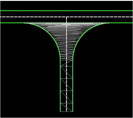
When you create the civil cell, the elements you used to create the terrain model, and the terrain model itself, will be included:
Now select the civil cell, and view it in Element Information. Expand the tree view node for Dependent Elements, and you will see the terrain model listed. Right click on it to show the pop-up menu, and select Add Boundary Terrain:

When the civil cell is placed, this terrain can be selected to clip the receiving corridor against.
In the situation described above, it is a good idea to include a boundary element across the top of the intersection, along the stop or yield line. This should be done to ensure that the shape of the clipping boundary is still correct if the reference element for the main road is curved.
Start and end locations
If you want to create an element in a civil cell that is a certain length, you could specify the start and end stations as Delta Stations using Civil Accudraw relative to a known location - typically an intersection of two elements.
If a civil cell is created at absolute stations these may not exist in the reciepent geometry and so the civil cell will not place.
Using Points
A 2D point can be used to locate a civil cell. In the case of an island for a pedestrian crossing for example, where the two sides of the island are parallel to a reference element, you want to be able to place it at any location along the reference element. This means that you should not specify start and end stations when you create the two sides because they would be stored in the civil cell, and it would always be placed at these stations. A better technique is to place a point, then place the elements to form the island relative to it. For example, create the offset transition elements for the sides of the island using offsets from the reference element, but define the start point by snapping to the point, and define the end point using a length. Now select the point and move it, and the two sides of the island will follow. When you create the civil cell, define the point as a reference element, so that you are prompted to select it when you place the civil cell. You do not have to create a point to do this, you can use a snap, or define the location of the point using Civil AccuDraw, or just use a datapoint, which means that you have lots of flexibility when defining the location.
There are other types of constructions that would also benefit from this technique - bus stops, traffic calming features, and merging / diverging ramps being just a few examples.
A 3D point can be used to achieve two objectives, because it can be used to not only locate a civil cell, but define elevations for it as well. In the case of a turning head for example, the geometry might consist of a circle, with two fillets to tie the turning head in to the end of the road. In this case, a point can be used to locate the centre of the circle, and if it is 3D, it can also be used to apply elevations to the circle. When the civil cell is placed, Civil AccuDraw can be used to snap to the profile of a suitable element, such as the centreline of the road for example, or a terrain model.
Civil AccuDraw
Civil AccuDraw provides the geometric constructions required to create fully constrained geometry in civil cells. It can constrain points using two ordinates which are relative to the elements they were constructed from, such as a distance or an offset constraint. An example of where this technique is useful is in creating a turn lane for an intersection, where you want the length to be from the intersection of the two road centrelines, for a certain distance. In this situation, the Delta Station option is likely to give the most flexible solution.
Testing Civil Cells
As you are creating civil cells test the geometric rules that will be captured. Once you have created all of the elements that you want to be in the civil cell, but before you create the civil cell itself, it is worthwhile thoroughly testing that the elements all react correctly to multiple changes. This can be done by moving the reference elements, and checking that all of the dependent elements also move. If any elements do not update correctly then this needs to be resolved before the civil cell is created.